How to connect the RT4-5GP/4 transmitter to a Paradox panel
A step-by-step guide for installers: which mode to use with Paradox MG, SP, E, Esprit and Digiplex EVO panels, how to wire and program the RT4-5GP/4 GSM/LTE transmitter and how to check the link to the monitoring centre.
What you need
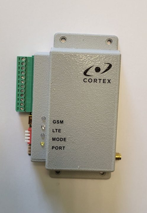
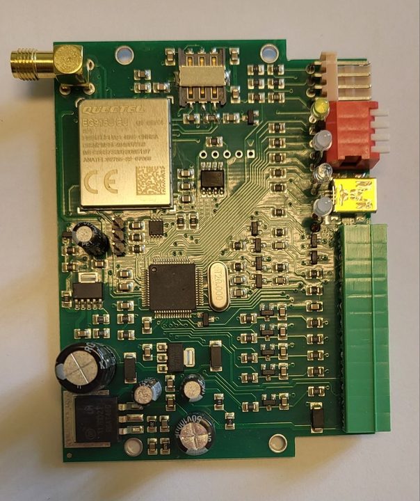
- An RT4-5GP/4 transmitter (a board for mounting in a cabinet) or RT4-5GP/4K (in its own enclosure) — both have the same functions.
- A Nano-SIM card with PIN 0000 or with the PIN request disabled. It is best to delete any contacts stored on the SIM.
- A GSM/LTE antenna with an SMA connector.
- A 9–15 V supply. Consumption at 12 V is 15 mA in SMS mode and 150 mA in OnLine mode.
- A mini USB to USB cable and USB_Reader 1.7.14 or later. Without a computer, the main settings can be made with SMS commands.
Which mode to choose
The RT4-5GP/4 communication port has eight operating modes. Three of them are used with Paradox panels:
| Paradox panel | Transmitter mode |
|---|---|
| MG, SP, E, including the «+» series | MG/SP/E |
| Esprit 7x8 series, version 3.00 or later | Esprit |
| Digiplex (EVO) | EVO |
- In all three modes the transmitter converts panel messages to Contact ID and sends them to the monitoring centre with its own account number.
- The mode is set with the DIP switch on the board. The switch combination is shown on the module label and in the manual, section “Operating modes”.
- DSC Power Series and CADDX NX panels are not wired to PORT but to terminals BL, YL and GR — modes DSC 1, DSC 2 and CADDX NX.
⚠ Change the mode only while the transmitter is powered off.
Wiring
The transmitter also has four general-purpose inputs IN1–IN4 (normally open by default), a mains power monitoring input IN5 (normally closed) and two open-collector outputs O1 and O2 rated up to 30 V and 1 A.
- Power off the panel and the transmitter.
- Set the DIP switch to MG/SP/E, Esprit or EVO as shown in the table above.
- Connect the panel serial port (SERIAL) to the transmitter communication port PORT — see figure 6 in the manual.
- Connect the 9–15 V supply to terminals 1 (−) and 2 (+).
- Connect the antenna. If you will set the transmitter up by SMS, insert the SIM card.
Programming with USB_Reader
- With the power off, connect the mini USB cable to the transmitter. The module enters programming mode and the MODE LED lights red.
- Enter the phone number of the first user (master) and the transmitter account number.
- To report to a monitoring centre, enter the server IP address and TCP port, the operator APN and the Online ID. The SIM card number is a convenient Online ID; if the field is left empty, the module writes the modem IMEI there.
- If needed, set a backup server (used when the link to the main server is lost) and a duplicate server (messages are sent to it in parallel, using the third user’s settings).
⚠ The Lock SIM option permanently binds the module to the first SIM card it detects. It can only be unbound at the factory, with proof of ownership. The Auto Upgrade enable option turns on automatic firmware updates.
No computer? Set it up by SMS
The phone must send SMS in text mode. One extra or missing character, even a space, and the module ignores the command. Once connected to the server, the remaining settings can be made remotely in TLF_Serv 2.3.0.6 or later.
- Insert the SIM card, power on and wait until the MODE LED lights green.
- From the phone that will become the master phone, send 91. followed by its own number. A number with a country code is written with «+»: 91.+37122334455. The module replies OK.
- Set the monitoring server: 99.I followed by the server IP address, then 99.P followed by the TCP port.
- Send 87.1234 — the command to connect to the server (1234 is the default security code).
Checking the installation
- MODE lights green — the transmitter is ready.
- GSM lights and flashes every 3 seconds — the transmitter is in OnLine mode. The colour shows the signal level: green — high, yellow — medium, red — low.
- LTE lights blue — the transmitter is on the 4G network. If it is off, the transmitter works on 2G.
- SMS 99.C4 returns the current mode (Mode) and connection state (Online). SMS 99.C3 returns the signal level CSQ: 15–20 is acceptable, 20–30 is good; CGREG must be 1,1.
- At the monitoring centre, create the site in WinSC: a unique transmitter account, the SIM number in the Phone field, and in the TLF Events tab load the RT4-5GP/4 cards and the descriptions for the connected panel.
Documentation
- 📄 RT4-5GP/4 V51.xx installation manual (Russian)
- 📄 RT4-5GP/4 V51.xx installation manual (Latvian)
- 📄 All manuals and software
This guide is based on the CORTEX manual. If you have questions, call technical support: +371 26485444 (24/7).