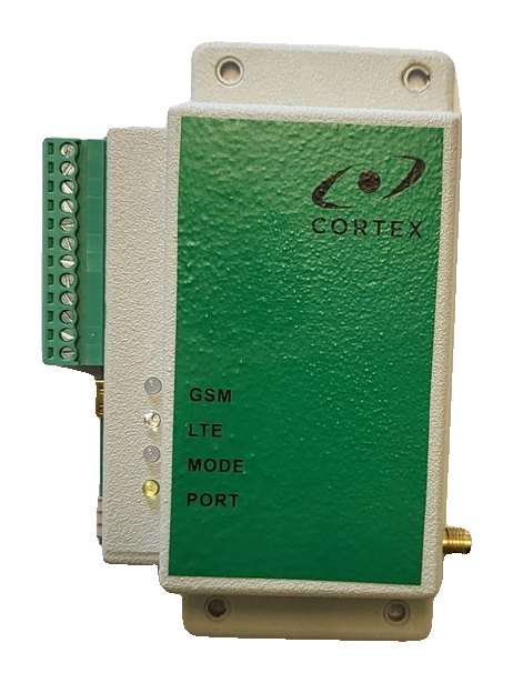
How to connect the RT4-5GT/4 to an alarm panel through its telephone communicator
The RT4-5GT/4 connects to the telephone (PSTN) communicator of an alarm panel and sends its events over 4G/2G. It suits panels of any brand that can “dial” a monitoring centre in Contact ID or SIA format. What to connect, how to set up the panel and how to check it.
How it works
- The transmitter emulates an ordinary telephone line: the panel “dials” the monitoring centre as before, and the RT4-5GT/4 receives the message and sends it to the server over 4G, falling back to 2G.
- Contact ID and SIA formats are detected automatically.
- Any telephone number can be programmed in the panel communicator.
- At the same time the transmitter accepts events from its own inputs and from the Serial BUS port, which takes interface modules and input expanders.
What you need
- An alarm panel with a telephone communicator supporting Contact ID or SIA.
- A Nano-SIM card with PIN 0000 or the PIN request disabled; it is best to delete contacts stored on the SIM.
- A GSM/LTE antenna with an SMA connector and a 9–15 V supply (15 mA in SMS mode, 150 mA in OnLine mode).
- A mini USB cable and USB_Reader 1.7.12 or later.
Transmitter terminals
| Terminal | Marking | Purpose |
|---|---|---|
| 1, 2 | −E, +E | 9–15 V power supply |
| 3–6 | IN1–IN4 | General-purpose inputs |
| 7 | IN5 | Mains power monitoring input or general-purpose input |
| 8 | COM | Common |
| 9, 10 | Tip, Ring | Panel telephone communicator |
| 11, 12 | O1, O2 | Outputs 1 and 2 |
Wiring
- Power off the panel and the transmitter.
- Connect the panel telephone line terminals TIP and RING to transmitter terminals 9 (Tip) and 10 (Ring) — see figure 5 in the manual.
- Supply 9–15 V to terminals 1 (−) and 2 (+).
- Connect the antenna, insert the SIM card and switch the power on.
Setting up the panel
- Enable the panel telephone communicator and select Contact ID or SIA format.
- Program any monitoring centre telephone number — the transmitter answers the call itself.
- Account: if the panel account is 9999, the transmitter replaces it with its own. Any other account is passed to the monitoring centre unchanged.
Programming the transmitter
- With the power off, connect the mini USB cable — the MODE LED lights red.
- In USB_Reader enter the first user’s phone number, the account, the server IP address and TCP port, the operator APN and the Online ID (the SIM number is convenient; an empty field is filled with the modem IMEI).
- Without a computer: from the master phone send 91. followed by its number, then 99.I and the IP address, 99.P and the port, and 87.1234 — the command to connect to the server.
Once connected to the server, the remaining settings can be made remotely in TLF_Serv 2.2.0.5 or later. The RT4-5GT/4 uses the same SMS commands as the RT4-5GP/4.
⚠ The Lock SIM option permanently binds the module to the first SIM card it detects; it can only be unbound at the factory.
Checking: the PORT LED
| PORT LED | Meaning |
|---|---|
| Steady yellow | The panel communicator is active — the panel has “gone off-hook” |
| Flashing yellow | A message is being received from the communicator |
| Single yellow flash | Data on the interface port |
| Continuous flashing about twice per second | Fault in the panel communicator or the line emulator |
- MODE green — the transmitter is ready; GSM lit and flashing every 3 seconds — OnLine mode; LTE blue — 4G network.
- Trigger an alarm on the panel: PORT lights and flashes, and the event arrives at the monitoring centre.
- Message E851000 (“PSTN comm fail”) means a communicator fault; E856000 (“Incorrect message from PSTN”) means an invalid message came from the communicator: check the format and the TIP/RING wiring.
Good to know
- SIA messages are not converted to text for SMS to a phone — in Text mode only Contact ID events and the transmitter’s own messages are sent.
- The transmitter’s own messages arrive with partition 99: input alarms E830001–E830005, test E823000, battery E822000.
- Firmware is updated with USB_Reader, automatically (Auto Upgrade enable) or by command — do not disconnect power while the LTE LED is flashing blue rapidly.
Documentation
Learn more
- RT4-5GT/4 or RT4-5GP/4: which to choose →
- Setting up the server connection (same commands) →
- Alarms in the Defendex app →
This guide is based on the CORTEX manual. If you have questions, call technical support: +371 26485444 (24/7).