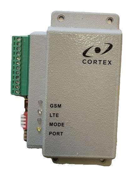
RT4-5GP/4 inputs and outputs: sensors, 220 V monitoring and load control
Besides the alarm panel connection, the RT4-5GP/4 has its own inputs and outputs: you can add extra sensors, monitor 220 V mains power and control a load — by SMS, by a phone call or automatically. What to connect where and how to set it up.
Transmitter terminals
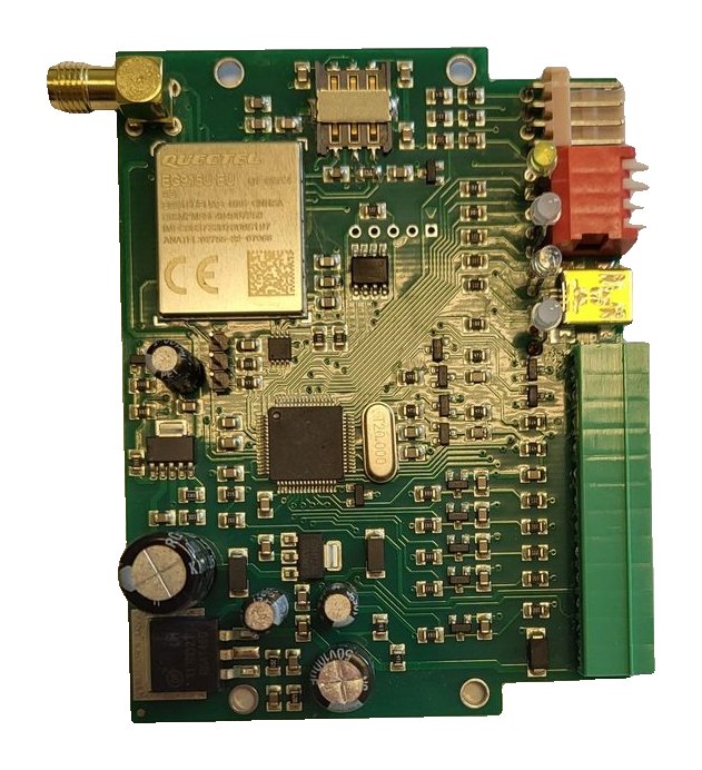
| Terminal | Marking | Purpose |
|---|---|---|
| 1, 2 | −E, +E | 9–15 V power supply |
| 3–6 | IN1–IN4 | General-purpose inputs |
| 7 | IN5 | Mains power monitoring input |
| 8–10 | BL, YL, GR | DSC and CADDX NX panel bus (BL — common) |
| 11 | O1 | Output 1 |
| 12 | O2 | Output 2 |
Paradox panels and interface modules connect separately — to the PORT communication connector.
Inputs IN1–IN4: extra sensors
- The inputs have internal pull-ups to the supply voltage and respond to “0”/“open” or “0”/“+” signals. The maximum input voltage is 15 V.
- By default inputs IN1–IN4 are normally open (NO). The type of each input (NO or NC) is changed in USB_Reader, Advanced Settings tab.
- An input alarm arrives with code 830, the input number as the zone and partition 99: for example, E83099003 — alarm on input 3; R830003 — restore.
- The event code of each input can be changed in the same Advanced Settings tab.
⚠ If an input is given its own event code, the zone number in the message is always 000. So do not give different inputs the same code other than 830 — the monitoring centre will not be able to tell them apart.
Input IN5: 220 V mains monitoring
- Input IN5 is normally closed by default and is intended for mains power monitoring.
- Mains loss is reported as E830005 (“Transm.: Alarm zone 5”), restore as R830005.
- The transmitter also watches its own supply: E822000 — battery low, R822000 — battery restored.
- On deep discharge, below 8 V, the transmitter stops sending messages and resumes at 11.5 V.
Outputs O1 and O2
The outputs are open-collector: up to 30 V on an inactive output and up to 1 A switched current. Connect loads above 1 A or 30 V, as well as 220 V mains, through an intermediate relay. The mode of each output is set in USB_Reader, Advanced Settings tab.
| Mode | When it switches on |
|---|---|
| User-controlled | By SMS command from a registered phone or from the monitoring software; can be switched on for a set time |
| PGM: no GSM network | Switches on when the GSM network is unavailable |
| PGM: no server link | Switches on when an IP connection to the server cannot be established |
| PGM: test | Switches on for 10 seconds when a test message is sent |
The outputs can also be used to reset external equipment automatically at regular intervals.
Controlling the outputs from a phone
| SMS | Action |
|---|---|
| 1 / 2 | Switch output 1 on / off |
| 1.xxx | Switch output 1 on for xxx seconds |
| 3 / 4 | Switch output 2 on / off |
| 3.xxx | Switch output 2 on for xxx seconds |
- By default users 1 and 2 control the outputs. The reply is “Output 1 activated” / “Output 1 deactivated” (E802001 / R802001), for output 2 — E802002 / R802002.
- A command can be assigned to a phone call: each user gets one command; the transmitter rejects the call and carries it out — for example, switching an output on for a set time. Set it up in USB_Reader 1.7.14 or later or TLF_Serv 2.3.0.6 or later.
Checking
- SMS 0 — the transmitter replies with the list of inputs in alarm, or “Battery OK” if all is normal.
- SMS 99.C4 — the IN field shows inputs in alarm, the OUT field shows active outputs.
- SMS 99.C2 — the operating modes of outputs OUT1 and OUT2.
Documentation
Learn more
This guide is based on the CORTEX manual. If you have questions, call technical support: +371 26485444 (24/7).