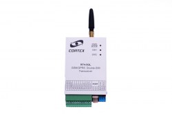
RT4-5GL/4: two SIM cards, a backup server and e-mail — setting up a redundant link
The main difference of the RT4-5GL/4 is its two SIM cards: if the main one stops working, the transmitter switches to the backup card by itself. How this works, what the SIM1 and SIM2 indicators show, and which commands set up both cards, the backup server and sending to e-mail.
Three levels of backup
| What is backed up | How |
|---|---|
| SIM card | The first card is the main one, the second the backup. If the first fails, the transmitter switches to the second and periodically checks whether the first works again |
| Server | Two IP addresses: main and backup. If the link to the first is lost, the transmitter connects to the second and periodically tries to return to the main one |
| Channel | If the first IP address is not set, the transmitter works in SMS mode |
- A domain name can be used instead of the main IP address.
- Information is sent to four users: to the first over the data channel or by SMS, to the others by SMS only.
- In data mode (the manual calls it GPRS mode) the transmitter does not send SMS to the first user.
How the two SIM cards work
- Insert two activated Micro SIM cards. If the PIN request is on, the PIN must be 0000. To work with one card, inserting the first is enough.
- At power-up the transmitter checks which cards are fitted. A missing card is not checked any further and its indicator stays off.
- If both are fitted, the transmitter works with the first. The SIM1 indicator shows the connection and signal level; the SIM2 indicator blinks green once every 10 seconds.
- If the first card fails, the transmitter switches to the second. SIM1 now blinks red once every 10 seconds and SIM2 shows the connection and signal.
- Together with the periodic test (once a day by default) the transmitter checks both cards and returns to the first when it can.
⚠ For correct work with two cards, enable the SIM2 check enable parameter in USB_Reader, on the Advanced settings tab. It is off by default.
SIM1 and SIM2 indicators
| Indicator | Meaning |
|---|---|
| Off | No SIM card fitted |
| On, blinking every 2–3 seconds | Data mode; the colour is the signal level: green high, yellow medium, red low |
| Only blinking every 2–3 seconds | SMS mode; the colour is the signal level |
| Blinking red once a second | Modem not initialised — check the SIM card |
| Blinking red once every 10 seconds | SIM card faulty |
| Blinking green once every 10 seconds | SIM card is working but not in use |
A POWER/MODE indicator that blinks red continuously means the transmitter is locked to other SIM cards.
Setup commands
All parameters are set in USB_Reader or by SMS commands from the first user’s phone.
| Command | What it sets |
|---|---|
| 99.A<APN> | APN of the first SIM card |
| 99.AA<APN> | APN of the second SIM card |
| 99.Y1<login>, 99.Y2<password> | Operator login and password for the first card, up to 8 characters |
| 99.YY1<login>, 99.YY2<password> | Operator login and password for the second card, up to 8 characters |
| 99.I<IP>, 99.P<port> | Main server IP address and TCP port |
| 99.II<IP>, 99.PP<port> | Backup server IP address and TCP port |
| 99.DD<name>, 99.DI<IP> | Domain name and DNS server address, if used |
| 99.M<min> | Time between attempts to restore the server connection; 3 minutes by default |
| 99.R<min> | Time between attempts to return to the main IP address; 60 minutes by default |
| 99.Wxxxx | Online identifier: digits only, up to 15 characters |
- The Online identifier must match the phone number of the main (first) SIM card without the international code. By default it is 11111111.
- Commands 99.Y1, 99.Y2, 99.YY1 and 99.YY2 without text delete the login and password.
Saving the battery: leaving data mode
| Command | When the transmitter leaves GPRS mode |
|---|---|
| 99.F0 | It does not leave until it receives command 86. with the security code |
| 99.F1 | If the battery voltage is below normal |
| 99.F2 | If the 220 V mains is lost |
| 99.F3 | If the battery voltage is below normal or the 220 V mains is lost |
- By default, leaving on low supply voltage is on and leaving on mains failure is off.
- On leaving, the transmitter sends E804000 (“Check bat or power”).
- Current at 12 V: 15 mA at rest and 150 mA in data mode.
Sending messages to e-mail
- The transmitter can send messages to an e-mail address. It sends what is configured in the message distribution for the third user; that user’s phone number does not have to be entered.
- Switch it on with the Email enable parameter in USB_Reader or TLF_Server, or with command 99.E1; switch it off with 99.E0.
- Set the SMTP server address and port, a login and password if required, and the recipient address.
- Only servers without TLS/SSL encryption are supported. If the server requires encryption, the message is not sent.
- The current e-mail settings are shown by command 99.C5.
Link messages
| Code | SMS text | Meaning |
|---|---|---|
| E854001 | GPRS 1 error | Data connection error on SIM1 |
| E854003 | GPRS 2 error | Data connection error on SIM2 |
| E854002 | Online 1 error | Error connecting to the server at the first IP address |
| E854004 | Online 2 error | Error connecting to the server at the second IP address |
| E855001 / R855001 | SIM 1 error / SIM 1 OK | First SIM card fault / restore |
| E855002 / R855002 | SIM 2 error / SIM 2 OK | Second SIM card fault / restore |
| E804000 | Check bat or power | Forced exit from data mode |
On a GPRS error check the APN and that the operator provides the service; on an Online error check the server IP address and TCP port.
Checking
- SMS 99.C3 — operator, signal level (CSQ: 15–20 acceptable, 20–30 good), data service availability (CGREG must be 1,1) and the settings of both SIM cards.
- SMS 99.C4 — the state of the cards (for example SIM1: ACTIVE, SIM2: BACKUP) and the Online line.
- SMS 99.C1 — addresses and ports of both servers and the ForceOff exit mode: 0 to 3.
- This article is based on the RT4-5GL V3.4 manual, which calls the data channel GPRS; the RT4-5GL/4 works in 4G and 2G networks.
Documentation
- 📄 RT4-5GL v3.4 user manual (Russian)
- 📄 RT4-5GL v3.4 user manual (Latvian)
- 📄 RT4-5GL v3.4 user manual (English)
- 📄 RT4-5GL v3.4 programming manual (Russian)
- 📄 RT4-5GL v3.4 programming manual (Latvian)
- 📄 RT4-5GL v3.4 programming manual (English)
Learn more
- RT4-5GL/4 as an alarm panel: zones and delays →
- Dallas keys, key-switch and arming by SMS →
- Antennas for CORTEX transmitters →
This guide is based on the CORTEX manual. If you have questions, call technical support: +371 26485444 (24/7).