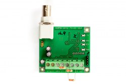
TX-63/RT transmitter: connecting a third-party alarm panel to an RS-63 VHF system
The TX-63/RT transmitter brings alarm panels of other makes into an RS-63 VHF system: it sends the receiver three alarm signals, the arming status and system faults. Terminals, zone types, programmable parameters and event codes. Based on the RS-63VHF V1.2 manual.
What the TX-63/RT sends
- Three alarm signals — on inputs Z1, Z2 and Z3.
- The status signal: arming and disarming.
- System fault messages: no mains power, transmitter supply below normal.
- Test messages, which the receiver uses to monitor the link to the site.
Terminals and indicators
| Terminal | Purpose |
|---|---|
| GND, +12V | Transmitter power |
| ARM | Information signal with the status of the connected panel |
| Z1, Z2, Z3 | Zone inputs: detectors or signals from the alarm panel |
| COM | Common |
| ACF | Information signal that mains voltage is present |
- TX indicator — a signal is being transmitted.
- RDY indicator — the panel is ready to arm (shows the status of the connected panel).
- ARM indicator on — the panel is armed.
- PWR indicator — transmitter power.
Detectors and panel signals are connected through the terminal block — the wiring options are shown in figures 15 and 16 of the manual. The recommended loop resistance is 3.3–3.6 kΩ.
Zone types
| Type | How it works |
|---|---|
| Delay | Ignored during the entry and exit delays; normally the entrance door. After the exit delay a trigger starts the entry delay |
| Instant | Ignored during the exit delay; after it, raises an alarm immediately |
| 24Hour | Always triggers, whatever the status of the site |
| Interior | After the delayed zone has triggered it behaves as a delayed zone; otherwise as an instant zone |
By default all three zones are programmed as 24Hour.
Programmable parameters
| Parameter | What it sets | Range | Default |
|---|---|---|---|
| ExD | Exit delay | 0 s – 20 min, step 5 s | 0 |
| EntD | Entry delay | 0 s – 20 min, step 5 s | 0 |
| Z_RT | Zone response time | 250 ms – 1 s, step 25 ms | 12 × 25 ms = 300 ms |
| AC_Abs_Time | How long mains voltage may be absent before it is reported | 0 – 20 min, step 5 s | 6 × 5 s = 30 s |
| Number of EventsPack | Number of transmissions per message | 3 – 6 | 3 |
| Test_Time | Test message period | 5 – 1200 min, step 5 min | 6 × 5 min = 30 min |
| Number of TestsPack | Number of test transmissions per session | 3 – 6 | 3 |
| Pan_Acc | Transmitter address, unique within the system | 1 – 63 | 1 |
| RR_adress | Address of the receiver the messages are sent to | — | 1 |
- The test period is counted from the last information message sent.
- A longer zone response time protects against interference, but short triggers — from magnetic contacts, for example — may be missed.
Event codes
| Event | Parameter | Default code |
|---|---|---|
| Alarm in zones 1–3 | Zone1_Trbl – Zone3_Trbl | 41, 42, 43 |
| Restore of zones 1–3 | Zone1_Rest – Zone3_Rest | 91, 92, 93 |
| No mains voltage | AC_Trbl | 81 |
| Battery voltage below critical | Accum_Trbl | 82 |
| Mains voltage restored | AC_Rest | E1 |
| Battery restored | Accum_Rest | E2 |
| Arming | Obj_Cl | C1 |
| Disarming | Obj_Op | B1 |
- If a parameter is set to FF, that event is not transmitted.
- For correct operation the codes in the IM-8 board and the RM-4 module must match the transmitter’s codes.
⚠ In the manual’s programming sheets the default arming and disarming codes differ: C1 and B1 for the TX-63/RT, C0 and B0 for the IM-8 and RM-4. Check that they match when you set the system up.
Programming
- Switch off the transmitter’s power: programming and reading are possible only with the power off.
- Connect a UsbPrg, UniPrg, UniPrg-cable or USP-16K programmer to the programming connector.
- Make sure the programming window shows the line Hardware->LPTx: Ready. The LPT port is selected with F9.
- Change the parameters with Space, or Ctrl+PgUp and Ctrl+PgDn. The allowed range is shown in the hint line of the window.
- Write the parameters with F5. They can be read from the transmitter with F6.
Checking
- On the receiver the REG indicator lights green during reception if the message came from a registered transmitter, and yellow if it is a test.
- The signal level indicator on the receiver should be yellow or green; red means the signal is too weak.
- Trigger an alarm in each zone and make sure it appears on the IM-8 board or in the monitoring software under the right address.
- Switch off the mains at the site: after the set AC_Abs_Time a message about missing mains voltage should arrive.
Documentation
- 📄 RS-63VHF V1.2 installation manual (Russian)
- 📄 RS-63VHF V1.2 installation manual (Latvian)
- 📄 RR-63 rev2 receiver installation manual, 2023 (Russian)
- 📄 RR-63 rev2 receiver installation manual, 2023 (Latvian)
Learn more
- RS-63 VHF system: components and how it works →
- Connecting the RR-63 rev2 receiver →
- Antennas for CORTEX transmitters →
This guide is based on the CORTEX manual. If you have questions, call technical support: +371 26485444 (24/7).