How to connect the RT4-5GF/4 to a Bentel or SmartLine fire panel
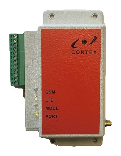
The RT4-5GF/4 is a GSM/LTE transmitter for fire alarm systems. It connects to the RS485 repeater bus of Bentel and SmartLine fire panels, detects the panel type itself and sends panel events to the monitoring centre in Contact ID format. How to wire it, what to set in the panel and how to check the link.
What the transmitter does
- Reads events from the RS485 repeater bus of SmartLine and Bentel fire panels; the panel type is detected automatically.
- Sends them in Contact ID format over 4G, falling back to 2G: to the main, backup and duplicate servers and by SMS to up to four users.
- Has 5 general-purpose inputs of its own and 2 open-collector outputs (up to 30 V and 1 A).
- Events from the panel and from its own inputs are accepted at the same time.
What you need
- A Bentel or SmartLine fire panel with a free RS485 repeater bus.
- A Nano-SIM card with PIN 0000 or the PIN request disabled.
- A GSM/LTE antenna with an SMA connector.
- A mini USB cable and USB_Reader 1.7.12 or later.
No separate power supply is needed: the transmitter is powered from the fire panel (supply range 9–30 V, 15 mA in SMS mode and 150 mA in OnLine mode).
Transmitter terminals
| Terminal | Marking | Purpose |
|---|---|---|
| 1, 2 | −E, +E | 9–30 V power supply |
| 3–7 | IN1–IN5 | General-purpose inputs |
| 8 | COM | Common |
| 9, 10 | −, + | RS485 bus |
| 11, 12 | O1, O2 | Outputs 1 and 2 |
Wiring
- Remove the terminal block from the transmitter — all connections are made on the removed block.
- Connect the panel RS485 bus to terminals 9 (−) and 10 (+).
- Connect +24 V from the panel to terminals 1 (−) and 2 (+) — strictly as shown in figure 4 of the manual. Bentel and SmartLine panels are wired the same way.
- Check the wiring and only then fit the block onto the transmitter.
- Connect the antenna and insert the SIM card.
⚠ Powering the transmitter from any other source is not allowed: it may damage the unit. Fit the terminal block onto the transmitter only after the wiring is finished.
Setting up the panel
| Panel | What to do |
|---|---|
| Bentel | No additional panel settings are required |
| SmartLine | After wiring, register the transmitter in the panel as the fourth repeater |
Programming the transmitter
- With the power off, connect the mini USB cable — the MODE LED lights red.
- In USB_Reader enter the first user’s phone number, the account, the server IP address and TCP port, the operator APN and the Online ID (an empty field is filled with the modem IMEI).
- Without a computer: from the master phone send 91. followed by its number, then 99.I and the IP address, 99.P and the port, and 87.1234 — the command to connect to the server.
Once connected to the server, the remaining settings can be made remotely in TLF_Serv 2.3.0.4 or later. The RT4-5GF/4 uses the same SMS commands as the RT4-5GP/4.
Checking
| PORT LED | Meaning |
|---|---|
| Flashing yellow | The link to the panel is established |
| Steady yellow | No link to the panel |
- MODE green — the transmitter is ready; GSM lit and flashing every 3 seconds — OnLine mode; LTE blue — 4G network.
- If PORT stays lit, check the RS485 bus polarity and, for SmartLine, whether the transmitter is registered as the fourth repeater.
- When the link to the panel is lost, E654000 (“Lost connect. to panel”) is sent to the monitoring centre; R654000 follows when it is restored.
- Trigger a test alarm on the panel: the monitoring centre receives E1100xx, where xx is the zone number.
The transmitter’s own inputs
All five inputs are normally open by default; the maximum input voltage is 30 V. The input type (NO or NC) and the event code are changed in USB_Reader, Advanced Settings tab. Input alarms arrive with codes E830001–E830005 and partition 99.
Documentation
Learn more
- Fire panel event codes →
- Setting up the server connection (same commands) →
- RT4-5GT/4 or RT4-5GP/4 for intruder panels →
This guide is based on the CORTEX manual. If you have questions, call technical support: +371 26485444 (24/7).