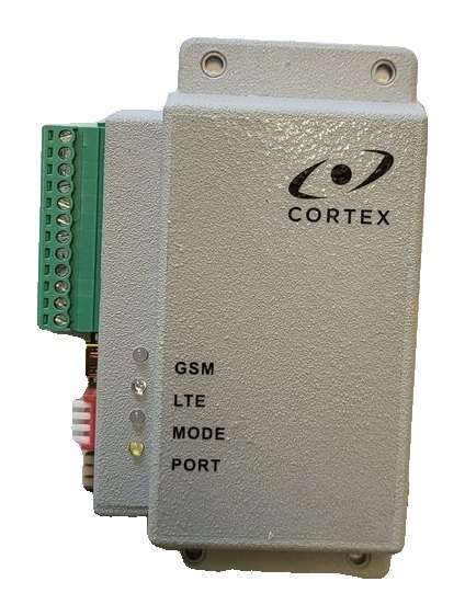
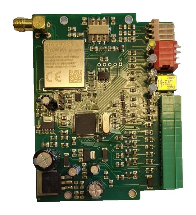
Connecting the RT4-5GP/4 to DSC Power Series and CADDX NX panels
The RT4-5GP/4 connects directly to the bus of DSC Power Series and CADDX NX panels, with no interface module. Which mode to choose, which terminals to use, what the monitoring centre receives and how to check it works.
Modes for DSC and CADDX NX
| Panel | Transmitter mode | Connection |
|---|---|---|
| DSC Power Series, 1–2 partitions | DSC 1 | Terminals BL, YL, GR — Key-BUS |
| DSC Power Series, more than 2 partitions | DSC 2 | Terminals BL, YL, GR — Key-BUS |
| CADDX NX | CADDX NX | Terminals BL, YL, GR — NX panel bus |
- In all three modes the transmitter converts panel messages to Contact ID and sends them with its own account number instead of the panel’s.
- The mode is set with the DIP switch on the board while the power is off. The combination is shown on the module label and in the manual section “Operating modes”.
- Paradox panels connect differently — to the PORT connector; there is a separate guide for that.
Connecting to DSC Power Series
- Power off the panel and the transmitter.
- Set the DIP switch to DSC 1 (panel with one or two partitions) or DSC 2 (more than two partitions).
- Connect the transmitter terminals to the panel Key-BUS: 8 — BL (common), 9 — YL, 10 — GR. See figure 7 in the manual.
- Supply 9–15 V to the transmitter: terminal 1 — negative, terminal 2 — positive.
- Connect the antenna and insert the SIM card, then switch the power on.
Connecting to CADDX NX
- Power off and set the DIP switch to CADDX NX.
- Connect the transmitter terminals BL, YL and GR to the NX panel bus as shown in figure 8 of the manual.
- Supply 9–15 V to terminals 1 (−) and 2 (+), connect the antenna and switch the power on.
⚠ For the NX panel to register the transmitter, enter the panel’s programming mode and exit it again.
What the monitoring centre receives
Panel events arrive in Contact ID format. The full code tables are in appendices 7 (Key-BUS, DSC) and 9 (CADDX NX) of the manual. The transmitter’s own messages arrive with partition 99.
| Code | Event |
|---|---|
| E130xxx / R130xxx | Alarm / restore in zone xxx (CADDX NX) |
| E110001 | Fire alarm (CADDX NX) |
| E120001 | Panic (CADDX NX) |
| E833020 / R833020 | Transmitter communication port failure / restore |
| E830001–E830005 | Alarm on transmitter inputs 1–5 (input 5 — mains power) |
| E822000 / R822000 | Battery low / restored |
| E823000 | Test report |
Checking the installation
- MODE lights green — the transmitter is ready; PORT flashes green while data is exchanged with the panel.
- SMS 99.C4 returns the current mode (Mode) — make sure it is the required DSC or CADDX NX mode.
- Message E833020 (“Port failure”) means a communication port fault: check the bus wiring and the selected mode.
- At the monitoring centre, load the RT4-5GP/4 cards and the descriptions for the connected panel into the TLF Events tab in WinSC.
Documentation
Learn more
This guide is based on the CORTEX manual. If you have questions, call technical support: +371 26485444 (24/7).