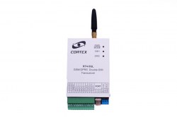
RT4-5GL/4 as an alarm panel: zones, delays and wiring
The RT4-5GL/4 transmitter can itself work as a small alarm panel: monitor the loops, switch on the siren and send alarms to the monitoring centre. How this mode works, how the inputs are assigned and what to set in USB_Reader.
How alarm panel mode works
- The transmitter monitors its inputs according to the arming state: “Disarmed” or “Armed”.
- When disarmed, only changes of 24-hour zones (24h) and of the power monitoring input (PWR) are sent to the monitoring centre. The other inputs are ignored.
- When armed, a zone trigger switches on the siren and sends a message to the monitoring centre. Zone restores are sent as well.
- The site is armed and disarmed with Dallas electronic keys, contactless keys or a key-switch. The reader or switch is connected to the transmitter’s interface port.
Inputs and outputs in panel mode
Some zones are fixed and their function cannot be changed.
| Terminal | Input or output | Function in panel mode |
|---|---|---|
| 4 | INPUT1 | Programmable zone |
| 5 | INPUT2 | Entry/Exit — a delayed zone with entry and exit delay, normally the entrance door |
| 6, 7, 8 | INPUT3–INPUT5 | Programmable zones |
| 9 | IN6/ACF | PWR — 24-hour input for 220 V mains monitoring |
| 10 | OUTPUT1 | Siren: in panel mode this output always works as Bell |
| 11 | OUTPUT2 | Output 2 |
| 1, 2 | −E, +E | Power supply 10–30 V |
| 3 | COMMON | Common |
| 12 | +E(OUT) | Supply for connecting the outputs |
The PWR input is connected to the ACF output of the VSCS-1,5 and VSC-3,0-12 power supplies or to the OUT output of the AC_detector device.
Programmable zone types
| Type | How it works |
|---|---|
| 24h — 24-hour | Always triggers and raises an alarm whether or not the site is armed |
| Interior | After the delayed zone has triggered it behaves as a delayed zone; if the delayed zone has not triggered — as an instant zone |
| Instant | Normally for door and window contacts: it has an exit delay and triggers immediately once that delay has ended |
Each programmable zone has a StayAway flag: whether the zone is ignored when arming in STAY ARM mode. The flag has no effect for a 24h zone.
Setting up in USB_Reader
- Set alarm panel mode with the DIP switch — the combination is shown in the manual, in the section on setting operating modes.
- Connect the USB cable to the transmitter. When the POWER/MODE indicator turns red you can start programming.
- Open the programming window (File/Read) and select the Panel mode tab.
- Set the delays: EntryDelay — entry delay, EntryDelayForStay — entry delay for STAY ARM mode, Exit Delay — exit delay, BellCutOff — siren time on alarm.
- For zones 1, 3, 4 and 5 choose the type (Z1 Type, Z3 Type, Z4 Type, Z5 Type) and the StayAway flag.
- KeySwitch checkbox: off — arming with electronic keys, on — with a key-switch.
- LinesWithSingleEOLResistor checkbox: on — loops with an end-of-line resistor, off — normally closed loops.
- Press OK — the parameters are written to the transmitter.
Loops and inputs
- In EOL mode the loop resistance in the normal state must be 6.8 kΩ.
- The input pull is set with a jumper: removed — inputs are pulled to “+” and react to “0”/open circuit; fitted — pulled to “0” and react to “+”/open circuit.
- Fitting the jumper inverts the state of all inputs.
- The maximum input voltage is 30 V. Outputs: up to 1 A, up to 30 V on a closed output.
- Wiring diagrams for the loops, the ACF input, the reader and the siren are in the manual’s section on connecting external devices to the transmitter.
What arrives at the monitoring centre
| Code | Restore | Event |
|---|---|---|
| E830001–E830005 | R830001–R830005 | Alarm in zone 1–5 |
| E830006 | R830006 | Mains power lost (“AC lost”) |
| E8400xx | R8400xx | Disarmed / armed by user xx |
| E8410xx | R8410xx | Disarmed / armed in Stay Arm mode by user xx |
| E8580xx | — | Guard xx touched the reader with a key |
| E821000 | — | An unregistered key was used |
| E822000 | R822000 | Battery supply below normal |
| E823000 | — | Test message |
The transmitter’s own messages arrive with partition 99.
Checking
- Send SMS 99.C4: in the reply Mode: panel means panel mode and PanStat is the arming state: D — disarmed, A — armed, StayA — armed in Stay Arm mode. The number in brackets is the user who last changed the state.
- The IN line of the same reply lists the inputs in alarm.
- Reader LED: steady on — disarmed and ready to arm; off — not ready; double blink every 2 seconds — armed.
- This article is based on the RT4-5GL V3.4 user manual and programming manual.
Documentation
- 📄 RT4-5GL v3.4 user manual (Russian)
- 📄 RT4-5GL v3.4 user manual (Latvian)
- 📄 RT4-5GL v3.4 user manual (English)
- 📄 RT4-5GL v3.4 programming manual (Russian)
- 📄 RT4-5GL v3.4 programming manual (Latvian)
- 📄 RT4-5GL v3.4 programming manual (English)
Learn more
- Dallas keys, key-switch and arming by SMS →
- Two SIM cards and a backup server →
- Power supplies in the catalog →
This guide is based on the CORTEX manual. If you have questions, call technical support: +371 26485444 (24/7).