RR-63 rev2 receiver: connecting a transmitter, a computer, IM-8 boards and RM-4 modules
The RR-63 rev2 receiver collects messages from the sites of an RS-63 system and passes them to the monitoring centre, a computer or an indication board. What to connect to it and how, what the indicators show, and how the IM-8 board and RM-4 relay module work. Based on the RR-63 rev2 manual (2023).
What can be connected
| Device | How many | Receiver port |
|---|---|---|
| Radio, GSM or I-Net transmitter | 1 | Serial Bus |
| IM-8 indication board | Up to 8 | RS-232 |
| RM-4 relay module | Up to 16 | RS-232 |
| Computer with Win SC software | 1 | RS-232 |
- The receiver works in RS-63/RT (433 MHz) and RS-63/VHF (139–174 MHz) systems. There is no functional difference — only the frequency range differs.
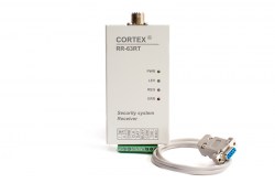
- The terminal block has three groups: power, the Serial Bus port for a transmitter and the RS-232 port.
⚠ If a computer is connected to the RS-232 port, boards and relay modules cannot be connected: the software uses a different data format.
Indicators
| Indicator | What it shows |
|---|---|
| PWR | Power is present. The LED is blue on the RR-63/RT and yellow on the RR-63/VHF |
| LEV | Received signal level during reception: red — poor, yellow — medium, green — good |
| REG | During reception: green — message from a registered transmitter, red — from an unregistered one, yellow — a test message |
| ERR | Exchange failure with the transmitter that passes information to the monitoring centre. Goes out after the next successful exchange; stays on if no transmitter is connected |
Connecting a transmitter for the link to the monitoring centre
- The receiver accepts: RT4-5se V3 and V4 radio transmitters, RT4-5gp, RT4-5gc V3 and RT4-5GL GSM/GPRS transmitters, and the RT4-5et I-Net transmitter.
- Any other device that supports the Serial Bus protocol will also work.
- Only one RR-63 rev2 receiver can be connected to one transmitter.
- The receiver connects to the transmitter port with a four-pin connector. The transmitter port mode must be Standart.
- GSM/GPRS transmitters can also send text SMS about events at the sites.
- The wiring diagram is in figure 3 of the manual.
Connecting a computer
- Use a TC-232 cable — it is supplied separately. The pinout is in the manual.
- In the receiver set RX_CONFIG (COM Format) to ASCII.
- Set RX_CONFIG (Baud Rate) to 9600.
Connecting IM-8 boards and RM-4 modules
- Boards and modules connect to the RS-232 port as shown in figures 4 and 5 of the manual.
- Several boards and modules are wired in parallel; the order does not matter.
- Boards and modules can be used together, including for the same transmitter addresses.
- The receiver must have RX_CONFIG (COM Format) set to Binary and RX_CONFIG (Baud Rate) to 2400.
Registration and link monitoring
- The receiver registers a transmitter automatically on its first test signal and then watches for tests from that address.
- If a test does not arrive in the set time, the receiver generates a “no test” message on behalf of that transmitter.
- If there are no messages for a long time, the receiver removes the address from the registered list and generates a “no link” message.
- Information messages are processed regardless of registration.
IM-8 board: what it shows
The board has 8 independent groups of indicators — one per transmitter. The sound is common to all.
| Group indicator | Meaning |
|---|---|
| Status, three-colour | Green — site disarmed, red — armed. Off — no status message has arrived yet |
| Inputs 1–3, red | Alarm on a transmitter input |
| System, yellow | No mains power (the ACF input of the TX-63/RT transmitter) |
| System, yellow | Low transmitter supply voltage |
| TEST, yellow | No test signal; blinks at double rate if there have been no signals from the site for a long time |
The board has NO relay contacts: they close on any alarm message from any transmitter.
IM-8 board: operator actions
- After power-up all indicators blink — press the button on the front panel and the board is ready.
- A zone alarm or system alarm switches on the sound and the indicator starts blinking. After the button is pressed the sound stops, the indicator blinks for 2 more seconds and then stays on.
- With factory settings the sound switches off by itself 10 minutes after the last alarm message (parameter Cutoff_Time). In Endless mode it sounds until the button is pressed.
- With factory settings only restores of system alarms are processed; zone restores are ignored.
- A status message comes with a short beep, about a second, and the status LED blinks until the button is pressed.
- After an arming message is confirmed with the button, the zone alarm memory for that site is cleared. The yellow system indicators do not change.
- To clear the indication of a site with a lost link, hold the button for about 4 seconds.
RM-4 relay module
- The module has 4 independent groups of outputs, each tied to the address of one transmitter.
- A group has a status output (disarmed / armed), zone outputs Z1–Z3, a power monitoring output and a test message monitoring output.
- The output type is set by jumper J2: fitted — all outputs are normally closed; removed — normally open.
- A system alarm, zone alarm or disarming activates the corresponding output; a restore or arming returns it to the normal state.
- The common alarm output is activated by an alarm in any zone of any group and returns to normal when all zone outputs in all groups are normal.
- To return all outputs to normal manually, hold button K1 for 2 seconds.
Documentation
- 📄 RR-63 rev2 receiver installation manual, 2023 (Russian)
- 📄 RR-63 rev2 receiver installation manual, 2023 (Latvian)
Learn more
- RS-63 VHF system: components and how it works →
- TX-63/RT transmitter: connecting a third-party panel →
- Win SC — monitoring centre software →
This guide is based on the CORTEX manual. If you have questions, call technical support: +371 26485444 (24/7).